
By Hamish Robertson, Low Voltage Drives and Automation – TECO Australia & New Zealand
Variable Speed Drives (VSDs), when engineered rigorously, transform industrial motor control by delivering precise operation, system-level efficiency, and reliability.
This article outlines key considerations, including efficiency enablers, thermal, mechanical, and electrical integrity, power quality, and integration, for EPC and control engineers to achieve predictable outcomes.
VSDs are a mature and widely implemented technology across modern industrial control systems. When applied with rigorous engineering discipline, they provide precise speed and torque control, enhanced process stability, and substantial system-level efficiency gains. This often far exceeds the motor’s nameplate performance alone.
For EPC contractors, utilities, design authorities, and engineering teams, the real value of a VSD is realised not in the device as a standalone component. It is realised in the predictability, reliability, and optimisation achieved when the motor, drive, driven equipment, and electrical network are engineered to operate as a fully integrated system.
This article presents a practical, system-level framework for specifying and applying low-voltage VSDs in industrial motor control applications. It details the key engineering considerations. I.e., thermal performance, mechanical reliability, electrical insulation integrity, power quality, and network integration, that deliver reliable, repeatable, and specification-compliant outcomes across diverse industrial environments.
Drawing on proven drive platforms, this approach transforms VSDs from standalone components into governed elements of engineered industrial solutions. This framework underscores how disciplined engineering elevates VSDs from mere components to integral system enablers.
A VSD does not increase the intrinsic efficiency of an electric motor. Instead, it enables the motor to operate at the speed and torque required by the process at any given operating point.
When speed/torque variations are aligned with load characteristics, particularly in variable torque applications such as centrifugal pumps and fans, VSD-controlled systems achieve significant reductions in total energy consumption.
For centrifugal pumps and fans (quadratic torque loads), power scales with the cube of speed as per the affinity laws:
For example: Using a VSD to reduce speed by 20% (to 80% of rated) cuts power to ~51% (0.8³ ≈ 0.512), yielding ~49% savings vs. throttling. These improvements result from overall system behaviour, not motor nameplate efficiency. They are achieved through controlled speed reduction rather than mechanical throttling or bypass methods, which waste energy through heat generation and pressure losses.
From the perspective of EPC and control system engineers, efficiency must therefore be evaluated at the driven-system level, ensuring that electrical, mechanical, and process objectives are addressed concurrently.
VSD platforms with wide operating frequency capability and defined overload margins allow engineers to implement control strategies based on process requirements rather than drive limitations.
The use of Direct-On-Line (DOL), Soft Starters, Liquid Resistance Starters or VSD operation all remain valid within modern industrial design practice.
The selection of either approach depends on process demands, network constraints, and mechanical system characteristics.
VSD-based systems provide:
These characteristics are particularly beneficial where mechanical stress management, frequent starting, or variable speed operation is required. Where controlled transient performance is critical, defined overload capability becomes a key design parameter.
VSDs typically offer 110–120% overload for 60 seconds in normal (variable-torque) duty and up to 150% (or briefly 200%) in heavy (constant-torque) duty, depending on the drive classification.
This allows transient process demands to be accommodated without excessive motor oversizing or instability caused by motor overload limitations at the system level.
In VSD-controlled motor systems, thermal behaviour is governed by the interaction between electrical losses, cooling method, and operating speed.
Most standard industrial induction motors rely on shaft-mounted cooling fans, with airflow proportional to speed. Effective engineering practice aligns duty cycle, load profile, and speed range with the thermal capability of the motor. Where continuous operation at reduced speed is required, cooling strategy and motor selection are treated as integral design parameters.
Drive selection also contributes to predictable thermal performance. The use of VSDs can allow engineers to consider motor designs, including higher pole count, and look to overspeed them to achieve short-term process requirements. This enables a higher-pole-count motor to operate at its more efficient design speed for the majority of the duty cycle, while overspeeding briefly for peak demands.
Modern VSDs generate controlled AC waveforms using high-frequency switching techniques. Long-term operational integrity can only be achieved through a coordinated approach encompassing:
Alignment between drive characteristics and installation layout is paramount. Cable runs exceeding 50–100 m often require mitigation, although thresholds vary with drive switching frequency, motor type, and voltage. Drive manufacturer curves should always be consulted for precise guidance.
Mitigation measures may include dV/dt filters to reduce high voltage peaks, commonly applied in the 100–300 m+ range. Sine-wave filters are generally preferred where cables cannot be replaced or where runs are extremely long. Output reactors may also be used to mitigate long-cable effects and limit motor winding stress.
Insulated bearings, insulated bearing housings, and shaft grounding brushes can be implemented to eliminate the risk of EDM (electrical discharge machining), also known as bearing fluting or EDM pitting, which may lead to premature bearing failure. When engineered together, these elements enable inverter-fed motor control systems to deliver consistent electrical performance and predictable operation throughout their service life in industrial duty environments.
VSD-controlled systems allow torque and speed to be applied smoothly and predictably, significantly reducing mechanical shock during starting, stopping, and load variation events. This controlled behaviour contributes to the extended service life of shafts, couplings, gearboxes, pipework, and other driven equipment.
While these benefits are not always easily quantifiable, they can substantially extend equipment life, often by a factor of 2–5x or more in high-cycle or shock-prone applications. Exact gains depend on the duty profile and baseline operating conditions.
At the system level, mechanical reliability is achieved through coordinated motor and drive selection, effective grounding practices, and precise mechanical alignment. Drive platform selection may also be influenced by the installation environment and enclosure requirements.
As power-electronic devices, VSDs introduce harmonics into the electrical network. Unmitigated systems typically produce THDi levels of 70–100%, which can often be reduced to 30–40% using basic line reactors or DC chokes. With advanced mitigation, such as Active Harmonic Filters (AHFs), THDi can typically be reduced to below 5–8%, supporting compliance with IEEE 519 limits at the point of common coupling.
In Australia, these standards are commonly applied alongside AS/NZS 61000.3.6 for voltage distortion. Power factor can also be improved toward unity with appropriate mitigation strategies.
When designing modern electrical systems, efficient harmonic management is critical for meeting distributor requirements, controlling project costs, and delivering robust long-term performance.
While Low Harmonic or Active Front End (AFE) VSDs have their place, they are often not the most practical or economical solution for multi-drive installations in industrial and infrastructure projects. AFE VSDs are generally best suited to single, high-power dynamic loads, particularly where regeneration is required or where strict point-of-connection limits apply.
However, AFE drives introduce several trade-offs. These systems are typically large and heavy, increasing switchroom size, structural loading, transport complexity, and associated costs. As an inline solution, they operate continuously regardless of load conditions, resulting in higher electrical losses, increased heat output, and greater air-conditioning demand. In many cases, AFEs are over-specified relative to local distributor limits, increasing capital expenditure without delivering proportional system-wide benefit.
By contrast, Active Harmonic Filters (AHFs) provide a more flexible, system-level alternative. Installed as a shunt-connected solution, AHFs dynamically mitigate harmonics to predefined targets aligned with network and distributor requirements. A single AHF can manage harmonics across multiple VSDs, making it a cost-effective option for complex plants and facilities. AHFs also deliver higher overall efficiency, lower heat loads, and reduced operating costs.
This approach provides additional secondary benefits, including smaller switchrooms, simplified logistics, and the ability to specify standard, compact, lower-cost VSDs. These advantages can reduce both upfront capital costs and spare parts inventory requirements. AHFs can also mitigate plant-wide neutral harmonic currents and are easily scalable as facility loads change over time.
For EPCs and engineering teams balancing compliance, constructability, and whole-of-life cost, AHFs offer a flexible and scalable harmonic mitigation solution engineered around overall infrastructure and project requirements, rather than the drive alone. Effective system integration should also consider distribution design, coordination with upstream equipment, and communication with plant automation systems.
Predictable project outcomes depend on a clear definition at the specification stage. For VSD-controlled motor systems, this includes:
Where space or simplicity is prioritised, select a VSD supporting both networked (e.g., Modbus, Profibus) and hardwired control on a common platform, providing defined control behaviour aligned with standard industrial duty profiles, while remaining consistent with system-level specification requirements.
Across industrial projects, a consistent engineering approach benefits from access to a complete range of VSDs designed for defined operating conditions and application requirements.
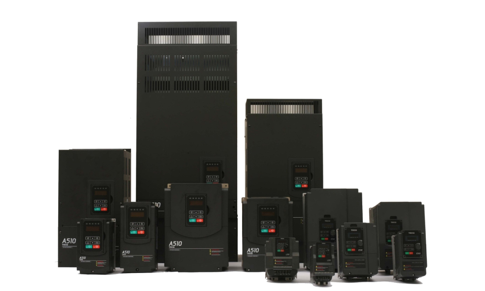
TECO’s low-voltage VSD offering includes models such as the A510 (heavy-duty vector control for demanding applications), E510 (general-purpose with advanced features), F510 (optimised for pump and fan variable-torque loads), alongside the E710 and compact L510s, selected based on installation requirements, environmental conditions, and application-specific constraints.
This portfolio-based approach allows EPC contractors and Control System Engineers to apply a consistent design philosophy while selecting the most appropriate VSD for each project application.
For EPC contractors, utilities, and Control System Engineers, the successful application of Variable Speed Drives is defined by engineering control rather than component selection.
When motor behaviour, thermal performance, electrical characteristics, mechanical integration, and network interaction are addressed as a unified system, TECO VSD-controlled installations deliver reliable, efficient, and predictable performance throughout their operating life.
A system-level approach, supported by TECO VSD platforms engineered with defined operating characteristics, transforms the Variable Speed Drive from a stand-alone device into a governed element of an engineered industrial solution.
TECO’s unified portfolio enables EPC teams to standardise on reliable, application-matched platforms while maintaining flexibility across project requirements.