
Wound rotor induction motors, also called slip ring motors, are used on mill drives because they give controlled starting under full load. The trade-off is the slip ring and brush gear, which need regular maintenance. Carbon brush wear is the part of that maintenance most likely to cause trouble. Left unchecked, the carbon dust it produces can lead to a flashover in the slip ring chamber, usually on the next start.
Brush wear depends on the site. Two operations running the same motor on similar duty can see very different brush wear rates. Loading and how long it is held, patina formation on the rings, how the chamber is cleaned, the oil feed to the bearings, brush grade and even the brush batch all affect the result. Some wear patterns can’t be fully explained, even with all the data in hand.
The first step is the full operating history: load profile, run hours, cleaning intervals and method, recorded wear rates, bearing issues, oil feed rate and pressure, and whether wear changes with the season.
A stable, shiny brown patina formed on the rings supports low, predictable brush wear. Rings that stay raw, with a bright bronze or copper colour, point to faster brush wear and wear on the slip ring surface.
At 100% load, a wear rate of about 3 to 4 mm per month is normal. TECO’s engineers consider 5 to 6 mm per 1,000 running hours ideal, and 8 to 10 mm per 1,000 hours is not uncommon. Wear rates vary from mine to mine, so use your own recorded rate as the baseline for setting the cleaning intervals.
TECO selects brush grade and brush numbers for best performance at 90% to 100% load. If a motor runs continuously below 90% load, the brushes can run too cold to form good patina and wear speeds up. De-brushing, which means taking some brushes out of service, raises the heat load in each remaining brush. The de-brushing chart is normally part of the machine’s certified drawing package.
Bearing oil is another cause. If the oil feed is too high in volume or rate, oil mist can reach the slip ring chamber. Oil mist with carbon brush deposits is abrasive to the ring surface and wears the brushes early. It also makes carbon stick, which can jam brushes in their holders, which can cause arcing between the brush and the slip ring.
Vacuum the enclosure while brushing down all internal surfaces with a dry paint brush, then wipe them with a clean cloth. Concentrate on the insulation between the rings and brush gear arrangement and remove all the carbon sitting there.
Never blow the chamber out with compressed air, even at reduced pressure. Air forces carbon into crevices and voids in the insulation, where it collects and conducts the next time high potential is present, typically during starting.
If the mill shuts down every 3 to 4 weeks, use that shutdown for a thorough clean by personnel trained on slip ring motors.
The slip ring chamber has its own air circuit, driven by a shaft-mounted fan, usually with a removable filter at the bottom or top of the chamber. Withdraw and clean it every 3 to 4 weeks, and more often if the motor runs lightly loaded and carbon dust is heavy. Once it is out of the motor, tap the excess carbon off the filter assembly, then blow the filter out with low-pressure air. If it is heavily contaminated, wash it in air-dry solvent or steam clean it, then let it dry.
Check the enclosure daily through the external windows. The person inspecting should know what to look for: excess dust contamination, worn brushes, excessive radial movement and any sparking between the brush and the slip ring.
During the shutdown, check that every brush moves freely in its holder. If one sticks, find out why. Usually it is carbon build-up jamming the brush, or the brush has swelled. Don’t mix brush grades or batches, because composite differences between batches can introduce selective wear.
Selective wear often follows brush position. The last brushes in the set on the same ring, called the lagging positions, can wear more because carbon from the brushes ahead settles and builds up next to them. On a motor running clockwise, viewed from the slip ring end, these are the last two positions to the right. Uneven wear can also show on the leading positions, depending on how the carbon spreads.
Record which positions wear most, on which ring, and whether the pattern repeats across all three phases. Check the pigtails for heat discolouration. Check that the connections from the brushes to the copper conductor plate, and on to the liquid resistance starter (LRS), are clean and tight. A heavily worn brush may be carrying more current.
Flashover in the slip ring housing is mostly linked to carbon dust build-up. Carbon conducts and allows tracking between phases, normally during the high potential starting sequence. The usual reasons for excess carbon deposits are:
The best protection is to keep the slip ring assembly and brush gear in very good clean condition at all times.
Insulation-test the rotor circuit. Test each slip ring to earth at around 500 V, then ring to ring. Keep the voltage low, because a tracking path will show at low voltage. Lift all brushes so only the slip rings and rotor winding are measured, unless you are certain the LRS is not shorting the phases.
Measure rotor resistance phase to phase. It will be very low, and it should be equal across the phases. Rotor circuits have an internal star or delta connection, so in a star configuration each reading may cover two phases. The check is that the resistances are all equal. Compare it with the value in the motor’s routine test report, using a meter that reads low enough.
When wear speeds up or turns selective, the cause is usually in the operating history. TECO builds and supports wound rotor mill drive motors, and can review yours against its certified drawing package and routine test report. For service work on site, TECO can recommend a service provider with suitable slip ring and brush experience.
Send TECO’s Electric Motors Division your motor details, load history and brush wear records to start the review.
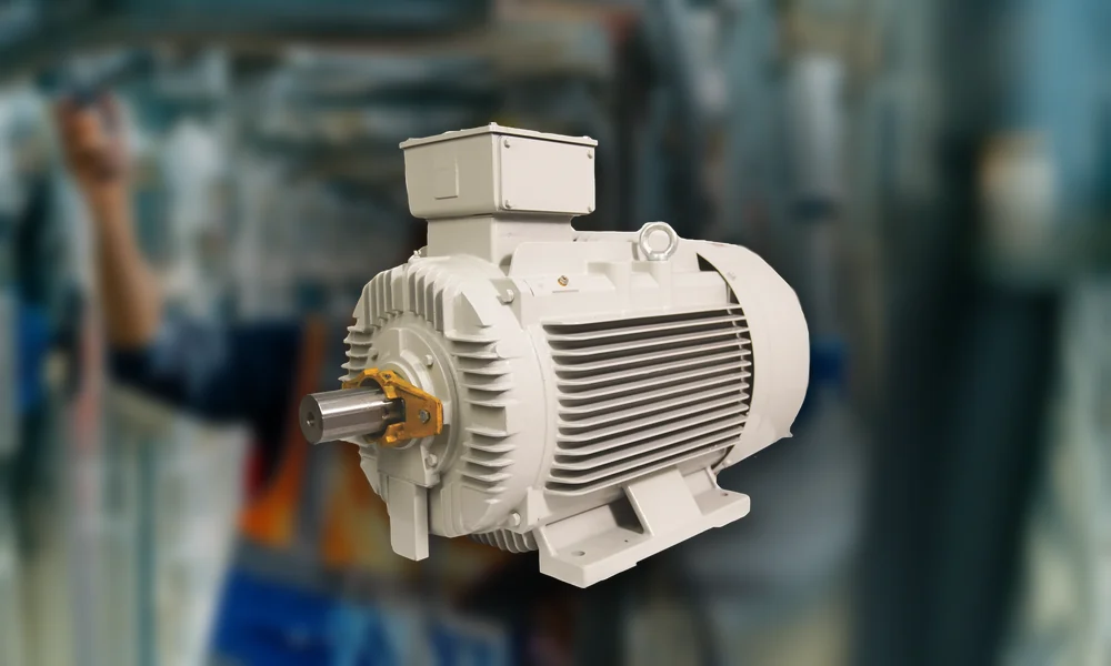
The TECO MAXeV4 is IE4 Super Premium Efficiency to IEC 60034-30-1 from 0.75 kW to 315 kW. At 0.75 kW 4 Pole it runs at 85.7% against 82.5% for an
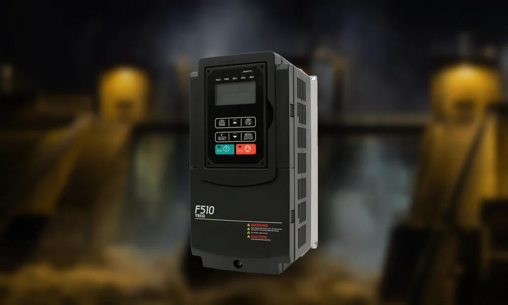
A variable speed drive (VSD) earns its place when pump flow demand varies throughout the day and the pump would otherwise be throttled or repeatedly cycled. In water and wastewater
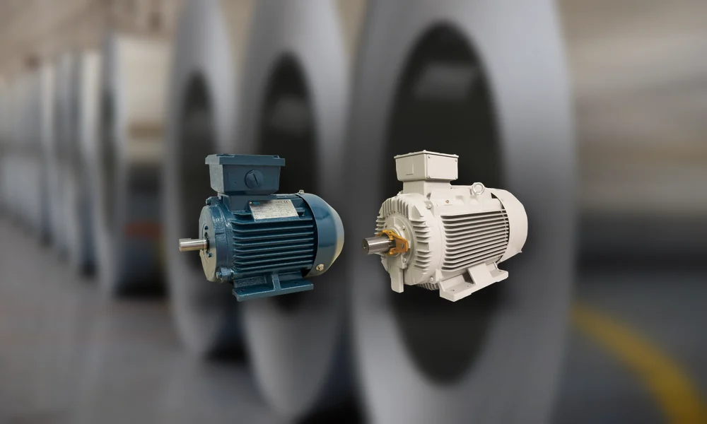
AS/NZS 1359 is the series of Australian and New Zealand standards that motor specifications and nameplates have referred to for decades. Many of its parts have since been superseded or