Most electrical engineers and industrial electricians have worked with low voltage (LV) motors throughout their careers, from a 4-copper-wire 15 V HVAC fan in an office building to an irrigation pump or a larger motor driving a conveyor at a mine site. Small and medium-sized LV motors like these are typically random-wound.
In random-wound motors, the winding consists of round copper wire coated with a thin layer of enamel insulation. The wire is wound directly into the stator slots, with the individual turns arranged randomly. This is where the term random wound comes from.
This construction is reliable and economical, making it well suited to the vast majority of LV applications.
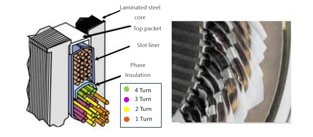
In a random wound stator, the copper wire goes into the slots without control over
which turns end up next to each other. At 415V, the voltage difference between adjacent turns is generally low enough for the enamel insulation on each conductor to withstand the electrical stress reliably.
This insulation system has stood the test of time and remains an economical, proven solution for low voltage motors.
However, as operating voltage increases, the electrical stresses between turns and between the winding and ground also increase, necessitating deliberate control. At these higher voltage levels, the stresses can exceed what conventional thin enamel insulation can reliably withstand over the life of the machine, so the conductor treatment must change.
At voltages such as 3.3 kV, random wound construction becomes increasingly difficult to implement reliably. Higher electric field gradients, particularly in the slot and end-winding regions, can contribute to partial discharge (PD) activity. Over time, this activity can progressively degrade the winding insulation and increase the risk of insulation failure.
This is why medium voltage motors use form-wound construction, which allows for a more controlled insulation system.
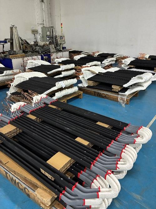
Form wound motors and generators solve this with pre-formed coils, usually made from rectangular cross-section copper conductors instead of round wire. Each coil is individually manufactured to an exact shape before it goes into the stator slots.
The insulation system is built in layers (Figure 3) rather than a single barrier. Depending on the voltage level, a dedicated corona protection layer is applied over the groundwall insulation in the slot region, and this is what manages the PD risk described above rather than tape thickness alone. The groundwall material is typically mica-based, chosen for its high dielectric strength and its resistance to the electrical and thermal stresses of decades of service.
Once wound, the coils are vacuum pressure impregnated (VPI) with epoxy resin, which substantially reduces the internal air voids that can initiate corona and long-term insulation breakdown. The insulation thickness is engineered and calculated for the voltage of the machine being wound. Because each coil is a pre-formed unit, the position of every conductor in the slot is known and controlled in the electrical design.
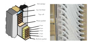
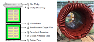
Figure 3 – Example of a typical form wound coil
A properly designed and manufactured form wound insulation system withstands MV operating stresses reliably over a long service life. Form wound coils can also be high-potential (hi-pot) tested individually before assembly, so winding defects are found before the machine is completed and varnished.
Form wound machines also have better slot fill. This means that there is a higher copper content in a given slot area compared to round wire due to the air gaps between conductors in a random wound stator. The improved slot fill allows motor manufacturers to improve the efficiency and power density of the machine.
Thermal performance benefits from the same changes. Better slot fill lowers winding resistance and reduces I²R losses, the resistive heating in the copper itself, at a given load. Void-free impregnation gives a more direct thermal path from the copper to the core, so whatever heat is generated escapes more efficiently.
This allows motor designers to increase power density at the same thermal class.
A standard 415 V irrigation pump motor will continue to commonly be random wound, and for good reason. It is simple, proven, and economical to produce. However, once voltages start to rise, form-wound machines take over, built for higher power, higher voltage, and the reliability those applications demand.